Schematic diagram of the compressed air cannons. Air is stored in the
Download scientific diagram | Schematic diagram of the compressed air cannons. Air is stored in the main tank, A. The pilot air supply, B, runs into a direct acting valve, C. When the valve is activated, the plunger lifts, allowing air into D, the piston valve head. This air pushes against spring E, raising the piston F, and allowing air release behind the projectile G. from publication: Development of Non-Explosive-Based Methods for Mass Capture of Vultures | Cannon- and rocket-projected nets have long been popular methods for mass capture of a variety of bird species. In recent years, obtaining licences to use the explosives required by these methods has become Increasingly difficult. We describe the construction of methods of | birds, Mass and Compressed Air | ResearchGate, the professional network for scientists.

Spray Guns: Getting Started - StewMac

9 gallon 212cc 135 PSI Wheelbarrow Air Compressor EPA

Schematic Diagram of the Compressed Air System
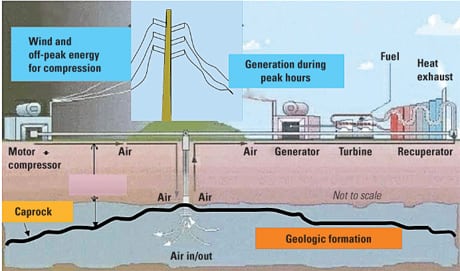
The return of compressed air energy storage
Air Cannon Air Blaster Block Clearer Bb6-20-30 High Temperature - China Air Cannon, Air Blaster
Air Compressor Buying Guide - The Home Depot
Air Cannons - Improve Flow in Silos & Storage Vessels

Ara MONADJEM, Professor (Full), PhD (University of Natal), University of Swaziland, Kwaluseni, UNISWA, Department of Biological Sciences
Compressed Air Cannon Home Model Engine Machinist Forum
IB Physics 2 Research Project

How to Make a Simple Air Cannon
Schematic diagram of air cannon structure.
AHAB Air Cannon Schematic Download Scientific Diagram